

Supported
by Photoshop Elements 11 and higher
Requirements:
Two or more image have to be opened.
Added in ElementsXXL
9
Executes the Match Zoom and Match Location commands at the same time. So if you have two or more images opened in Photoshop Elements, they will all receive the same zoom level and scrolled to the same image area. This helps comparing them better. Normally you need to apply both Match commands, so this new menu item saves you some time.
Supported
by Photoshop CS2, CC, 2020 and higher
Supported by Photoshop Elements 11 and higher
Requirements: None
Added in ElementsXXL
3.50
You can use these to make the ActionsXXL and FilterHub panels appear or disappear again.
Supported
by Photoshop Elements 11 and higher
Requirements: An image has to be opened.
Added in ElementsXXL
6.0, extended in 7.0 and 8.0
ElementsXXL displays icons on the Adjustments panel of Photoshop Elements if no adjustment layer is selected on the Layers panel. Once an adjustment layers is selected in the Layers panel, the icons vanish and make room for the controls of the adjustment layers. After selecting a non-adjustment layer, the icons appear again.
Clicking on one of the icons lets you quickly apply the 8 adjustment layers of Photoshop Elements (the first two rows) as well as the adjustment layers of ElementsXXL (the next three rows). If you have AdjustShop installed, you will also see its fill and adjustment layers as icons at the bottom. The labels are hidden then to make room, but a tool tip with the name appears when moving the mouse over them.
To run the appropriate adjustment layer, click its icon. Alternatively use the menu icon in the top right corner and select an adjustment layer from the appearing menu.
Instead of displaying the options of ElementsXXL adjustment layers in a separate window, most of them are by default displayed directly on the Adjustments panel since ElementsXXL 7 (The exception are the Color Lookup, Replace Color and Range Adjust adjustment layers). This has the upside that you can edit the adjustment layer option must faster as you do not need to click to display the dialog and do not have to close it.


To use the ElementsXXL adjustment layers with their own dialog again, you have to activate the "Display adjustment layer dialogs" option on the Tools page of the ElementsXXL Preferences. Alternatively simply hold down the Ctrl key and click on an icon. Holding down the Ctrl key also works when clicking the menu item of an adjustment layer. To run the filter version of these adjustment layers you have to hold down the Shift key and click on an icon.
If the Adjustments panel is not displayed, you can either run it from the Windows > Adjustments menu, double click the thumbnail of an adjustment layer in the Layers panel or right click on adjustment layer in the Layers panel and select "Edit Adjustment". Once you have the Adjustments panel displayed, you only have to select the an adjustment layer in the Layers panel to display its controls. Each change is immediately applied to the adjustment layer.


All ElementsXXL adjustment layer controls, which are displayed on the Adjustment panel, have two icons in the top right corner. The first icon with the back arrow makes the current controls vanish and displays the icons for adding new adjustment layers again. This way you do not need to click on an image layer to display them again. The second menu icon displays a menu with various items. The Auto Options menu item of Curves adjustment layer displays the Auto Options dialog. The Curve Display Options menu item lets you customize the look of the Curves diagram. The following menu items are available for all ElementsXXL adjustment layers: The Display Adjustment Layer Dialogs menu item lets you activate the ElementsXXL Preference feature of the same name, which makes the adjustment layer controls display in their own dialog and not on the Adjustments panel itself. This can be reversed again in the ElementsXXL Preferences. The Show Icons item has the same purpose as the first icon and shows the icons of all adjustment layers again. The Help menu item displays the appropriate place in the manual similar to the ? button on my dialogs.
Supported
by Photoshop CS2, CC, 2020 and higher
Supported by Photoshop
Elements 11 and higher
Requirements: An image has to be opened.
Added in ElementsXXL
9

The Auto Correction panel offers various automatic photo correction features in one place. They are provided by Photoshop Elements as well as ElementsXXL. Click on the bottons to apply them with one click. The Undo button lets you undo the last applied correction. The Undo All button undoes all corrections that were applied via this panel. To perform a manual correction activate the Manual check box. This will display the dialog of the appropriate correction feature after clicking a button.
The two Smart Fix buttons apply multiple corrections at once. The XXL Correct does something similar, but is peformed by ElementsXXL itself. The Levels, Contrast and Brightness bottons try to improve the black/white points, contrast or brightness of the current image.
Color Correct applies the color correction feature of Photoshop Elements. The Color 1-3 buttons color run ElementsXXL's color correction featurs. They try to detect a color cast in different tonal areas of the image, so they produce different results. The Saturation button automatically increases or decrases the saturation.
The buttons under the Physical group perforn dehazing, lens correction, remove red eyes, reduce camera shake, apply noise reduction or smooth skin areas. Sharpen applies the auto sharpening of Photoshop Elements. XXL Sharpen applies ElementsXXL's more sophistcated sharpening feature. The Micro Contrast button enhances contrast in small details via ElementsXXL's Micro Contrast filter.
Supported by Photoshop Elements 11 and higher
Requirements: A tool that uses a brush has to be selected
Added in ElementsXXL
4.0
The Brush panel gives you access to 80 new brush features that otherwise not accessible in Photoshop Elements. It can also be displayed by clicking the "More Options..." button on the Tool Options window.
The Brush panel can be used with the following 22 tools:
The Brush panel offers a list at the left-hand side, which works similar to tab buttons. Clicking each list item displays new controls and also activates the check box of the item (except for the first two items). You can deactivate these settings again by deactivating the check box of the list item. The "O" letter at the right-hand side of each list item means that its settings are open and not locked. As a result they can be overwritten when clicking on a brush preset. If you click on the "O" it is turned into a crossed out "Ø" sign, which means that the settings are locked and will not be overwritten by a brush preset. The three items at the bottom ("Noise" up to "Built-up") of the list are only check boxes and do not display any other controls. Five tools (Quick Selection, Healing Brush, Smart Brush, Color Replacement and Background Eraser) support limited brush settings, in which case this list is disabled and only the Brush Tip Shape controls are usable.
Please note: ElementsXXL cannot access all brush settings at all times due to limitations of the plugin interface of Photoshop Elements. So during a Photoshop Elements session either only use the Brush/Tablet Settings dialogs of the Tool Options window or only use ElementsXXL's Brush panel, because adjustments in the Brush/Tablet Settings dialogs will be undone by a new adjustment in the Brush panel.
Previewing the Brush Adjustments
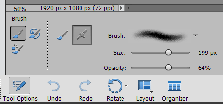
The best method to see if your adjustments on the Brush panel have the effect that you intend is to draw with the brush on the image. If you want to see a brush stroke preview, please display the Tool Options window by clicking the Tool Options button and have a look at the brush thumbnail displayed there. The thumbnail changes with every adjustment made on the Brush panel.
Brush Presets
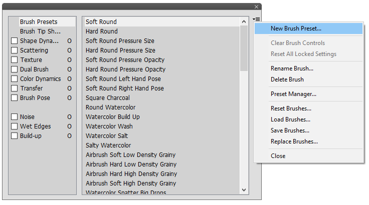
The Brush Presets item at the top displays a list with the
currently available brush presets. You see the same preset list if you click
on the Brush combo box on the Tool Option window of most of the above mentioned
tools. The icon in the upper right corner displays a menu with various option
for creating, renaming, deleting, resetting, opening and saving brush presets.
Brush Tip Shape
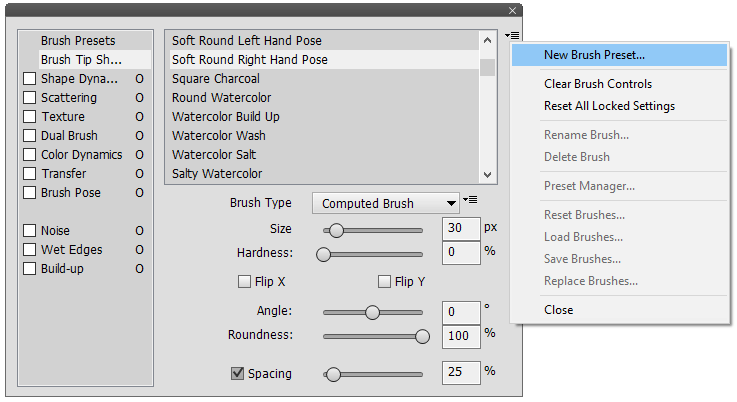
The Brush Tip Shape item displays controls for adjusting the brush tip. The list at the top lets you change the brush tip by selecting a brush preset. Unlike the preset list of the Brush Presets item clicking an item in this list will only change the Brush Tip Shape controls and not all controls of the Brush panel.
Photoshop Elements 13 and higher supports four brush types: Computed, Sampled, Erodible and Airbrush. Photoshop Elements 12 and lower only support computed and sampled brushes. The Bristle brush type of Photoshop is not supported by Photoshop Elements yet. Computed brushes are simple circular brushes that are calculated by an algorithm. Sampled brushes use a grayscale image for the brush tip and can be created with the Edit > Define Brush menu item. Erodible Tip brushes simulate a tip that wears off, e.g. like a pencil. Finally, Airbrush brushes imitate the properties of an airbrush. When you click on a preset in the Brush Preset section or the list of the Brush Tip Shape sheet, the Brush Type combo box displays the current brush type. You can use this combo box to switch to another brush type. Different controls are displayed for different brush types.
Computed & Sampled Brush Controls
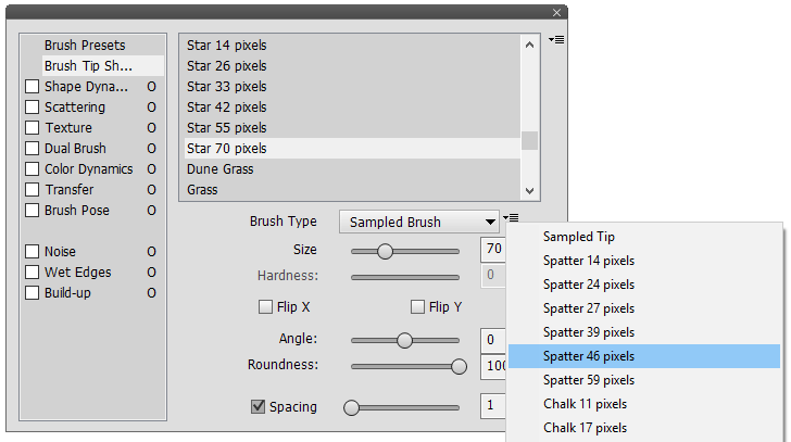
Computed and sampled brushes use the same controls. However, for sampled brushes the Hardness slider is not usable, but you can switch between various sampled tips. To do that click the menu icon at the right-hand side of the Brush Type combo box. The appearing menu indicates the currently used brush sample with a check mark and lets you switch to another brush sample. The other controls lets you adjust the size, hardness, angle, roundness and spacing of the brush imprints as well as flip the brush tip shape in horizontal and vertical direction.
Erodible Tip Controls
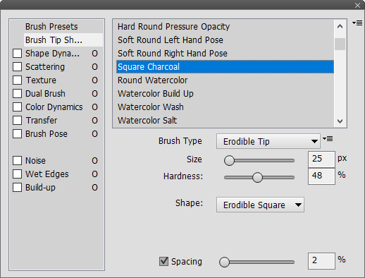
The controls of the erodible tip brush type let you adjust the size, hardness, shape and spacing of the brush tip. You can choose between point, flat, round, square and triangle shapes. These settings are only available in Photoshop Elements 13 and higher.
Airbrush Controls
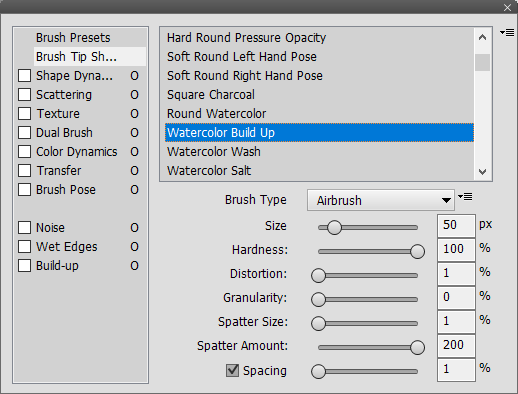
The controls of the airbrush type let you adjust the size, hardness, distortion, granularity, spatter size, spatter amount and spacing of the brush tip. These settings are only available in Photoshop Elements 13 and higher.
Shape Dynamics
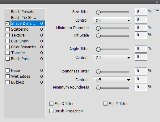
The Shape Dynamics sheet offers controls for dynamically changing the brush shape while painting with a brush tool. The Size Jitter slider determines how much the size of the brush shape varies randomly. The Control combo box defines if the brush shape variation is not controlled (Off), faded over time or controlled by the pen pressure, pen tilt or stylus wheel of a graphics tablet. If you choose the Fade option, you can also enter a value between 1 and 9999 for defining the fade out duration. The Minimum Diameter slider defines the minimum diameter that the brush shape must have when it is controlled. The Tilt Scale slider is only usable if you selected "Pen Tilt" in the Control combo box and lets you adjust how much influence the tilt has on the brush shape.
The Angle Jitter slider determines how much the angle of the brush shape varies randomly. The Control combo box defines if the angle variation is not controlled (Off), faded over time, controlled by the pen pressure, pen tilt, stylus wheel or stylus rotation of a graphics tablet or by the initial direction or direction of the brush stroke. If you choose the Fade option, you can also enter a value between 1 and 9999 for defining the fade out duration.
The Roundness Jitter slider determines how much the roundness of the brush shape varies randomly. The Control combo box defines if the roundness variation is not controlled (Off), faded over time or controlled by the pen pressure, pen tilt, stylus wheel or stylus rotation of a graphics tablet. If you choose the Fade option, you can also enter a value between 1 and 9999 for defining the fade out duration. The Minimum Roundness slider defines the minimum roundness that the brush shape must have. The Flip X Jitter and Flip Y Jitter check boxes flip the brush shape randomly and the Brush Projection check box allows the brush shape to be projected.
Scattering
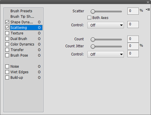
The Scattering controls lets you adjust the scattering of the brush tip imprints along brush stroke. You can compare it with the trembling hand of a painter. The more the hand trembles the more the imprints will vary orthogonal to the brush stroke and the thicker the line will become. The Scatter amount is controlled by the Scatter slider and the Both Axis check box also varies the scattering in the direction of the brush stroke and not only orthogonal to it. The Control combo box defines if the scattering is not controlled (Off), faded over time or controlled by the pen pressure, pen tilt, stylus wheel or stylus rotation of a graphics tablet. If you choose the Fade option, you can also enter a value between 1 and 9999 for defining the fade out duration.
The Count slider fills up the empty spots (where the brush tip did not hit the canvas) produced by the scattering. The higher the Count slider value, the less empty spots remain and the more consistent the brush stroke looks. The Count Jitter determines the randomness of the filling process and the Control combo box controls this process with different options.
Texture
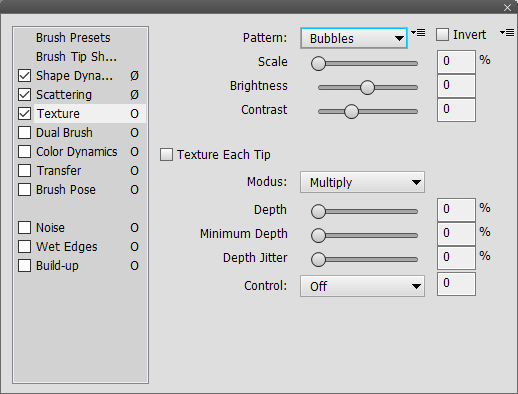
The Texture settings apply a texture effect to the brush tip. You can choose
one of the current patterns from the Pattern combo box. The
menu icon at the right-hand side displays a menu for opening
other pattern files. The pattern can be inverted, scaled, brightened and contrast
adjusted with the appropriate controls.
An activated Texture Each Tip check box blend the texture with each tip imprint rather than the whole brush stroke itself. The Mode combo box determines the blend mode that is used to blend the texture with the brush tip. For regular blend modes the Depth slider works like an opacity slider. For the Height and Linear Height modes, it works more or less the opposite way: Lower Depth slider values produce a texture look whereas higher slider values only only vary the brush tip shape.
With an activated Texture Each Tip check box you can also adjust with the Depth Jitter slider how much the texture depth randomly varies for each brush imprint. The Control combo box defines if the texture depth variation is not controlled (Off), faded over time or controlled by the pen pressure, pen tilt, stylus wheel or stylus rotation of a graphics tablet. If you choose the Fade option, you can also enter a value between 1 and 9999 for defining the fade out duration. The Minimum Depth slider defines the minimum depth of the texture blending.
Dual Brush
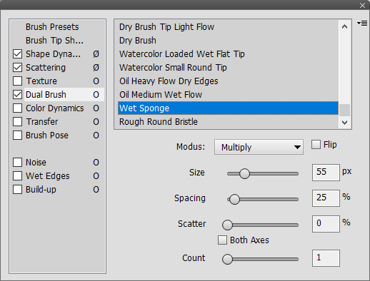
The Dual Brush controls let you define a second brush tip, which is blended
with the first brush tip. The controls here are similar to those of the Brush
Tip Shape and Scattering items. You can select a brush preset for the second
brush tip from the list at the top. You can adjust the size and hardness as
well as flip it. Additionally there are Scatter and Count sliders and a Both
Axis check box as described above. The Mode combo box contains the blend mode
with which both brushes are blended.
Color Dynamics
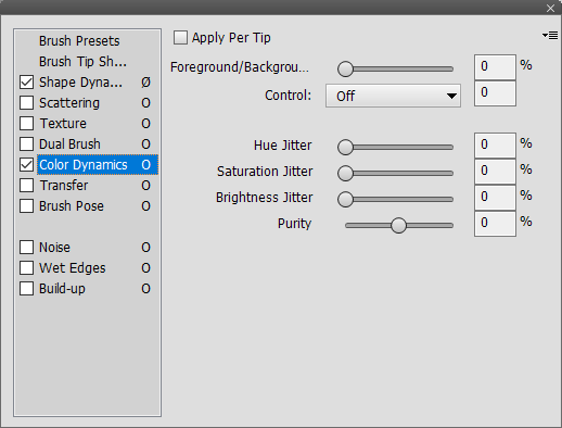
The Color Dynamic sheet lets you modify the color of the brush tip. The Apply
per Tip check box changes the color for each tip imprint. Otherwise
a different color is used for each new brush stroke.
The Foreground/Background (Jitter) slider increases the random variation of the color between the foreground and background color, which are displayed on the tool bar. The Control combo box defines if the color variation is not controlled (Off), faded over time or controlled by the pen pressure, pen tilt, stylus wheel or stylus rotation of a graphics tablet. If you choose the Fade option, you can also enter a value between 1 and 9999 for defining the fade out duration. The Hue, Saturation and Brightness Jitter sliders determine how much the hue, saturation and brightness of the brush color vary randomly. The Purity slider more or less adjusts the saturation of the brush color.
Transfer
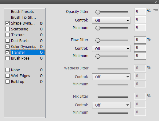
The Transfer controls influence the build-up effect. In the real word this correlates
with the absorption rate of the canvas and the liquidity or dryness of the paint.
The Opacity Jitter slider randomly varies the opacity of each
brush tip imprint. The Control combo box defines if the opacity
variation is not controlled (Off), faded over time or controlled by the pen
pressure, pen tilt or stylus wheel of a graphics tablet. If you choose the Fade
option, you can also enter a value between 1 and 9999 for defining the fade
out duration. The Minimum slider defines the minimum opacity.
The Flow Jitter slider randomly varies the flow speed of the brush stroke. The second Control combo box provides methods for controlling the flow speed. The Minimum slider defines the minimum flow speed.
The Wetness and Mix controls are only usable with the mixer brush tool (in Photoshop Elements 13-14). The Wetness Jitter slider randomly changes the "Wet" property of the mixer brush (see the Tool Options window). The third Control combo box provides methods for controlling the wetness. The Minimum slider defines the minimum wetness percentage. The Mix Jitter slider randomly changes the "Mix" property of the mixer brush. The forth Control combo box provides methods for controlling the mixing. The Minimum slider defines the minimum mixing percentage.
Brush Pose
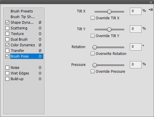
The Brush Pose settings controls allows you to adjust or override the input
from the stylus of a graphics tablet. If you use a mouse, these settings have
no effect. If the Override check boxes are activated, the horizontal
and vertical tilt, rotation and pressure of the stylus are adjusted according
to the respective slider values. The four sliders define the
maximum horizontal and vertical tilt of the stylus as well as its maximum rotation
and pressure.
Noise, Wet Edge and Build-up
The three check boxes at the bottom of the list display no controls. You can
only activate, deactivate and lock or unlock them. The Noise check box
adds a noisy edge to the brush tip. The Wet Edge check box
adds outlines to the brush stroke by brightening the bigger inner part
of the brush stroke. Finally, the Build-up check box enables
an airbrush-like build-up effect.
Supported by Photoshop Elements 11 and higher
Requirements: An image has to be opened.
Added in ElementsXXL
3.0

Clicking the Channels menu item displays the Channels panel. You can also double click the thumbnail of a layer in the Layers panel to display it. The panel window also includes a tab sheet for switching between the Channels, Paths and Properties panels. They are discussed below. To enlarge the panel window move the mouse arrow to the edge of the window and drag its border.
The Channels panel is an extended version of the Image > Channels sub menu. Besides the color channels of the image it also displays saved selections (see Select > Save Selection), which are stored as so called alpha channels, as well as the layer mask and filter mask of the currently selected layer.
To select a channel click on it in the channels list. If you click the RGB item at the top, the Red, Green and Blue channels will be automatically selected. But you can also select the Red, Green and Blue channels individually, which makes the other color channels invisible, so you will only see a grayscale image. To see the image in color again click the RGB item. To have one of the Red, Green or Blue channels selected and the image displayed in color at the same time, please click on the crossed out eye icon of the RGB item. Alternatively choose Image > Channels > Show All from the menu.
If you click on an alpha channel you will see it as a grayscale image in the document window. An alpha channel is a grayscale image that is not part of the image itself like the Red, Green and Blue channels. It can be used for masking image areas by turning it into a selection or layer mask. To display an alpha channel together with the image, click on the crossed out eye icon of the RGB item. Alternatively choose Image > Channels > Show All from the menu. Now you will see the alpha channel in red color on top of the image. If you prefer to see the alpha channel with another color, choose Channel Options from the panel menu. To select more than one channel hold down the Shift key and click on the other channel.
Right clicking on a channel selects it and displays a context menu, which is similar to the panel menu.
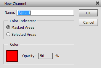
The New button as well as the New Channel menu item of the panel menu add a new alpha channel to the document. In the New Channel dialog you can enter a new name for the new channel, choose the color and opacity that is used when it is displayed together with the image and decide if this color should cover the masked or selected areas. Finally click OK.
Once the new channel is created, it will be displayed with black color in the document window, which means that the channel is masking the whole image. As it is usually better to also see the image together with the new channel, please click on the crossed out eye icon of the RGB list item. As a result you will see the channel as red (or the color you chose previously) on top of the image. You can now start editing the channel, e.g. by painting with the brush tool with a white foreground color or by drawing a selection and filling it with white color. But you can also go the other way around and start by creating a selection and saving it as an alpha channel. See the Save Selection menu item below.

The Duplicate Channel menu item of the panel menu lets you create a new copy of the selected channel. On the Duplicate Channel dialog you can enter a new name for it. Additionally you can choose to invert the channel by activating the Invert check box.

By default the current document is selected in the Document combo box. If you choose the New item in this combo box, a new document will be created and the channel copied to it. If another document with the same width and height as the current document exists, this document is also selectable from the combo box. By choosing it you can copy the channel to the other document.
The Delete button simply deletes the currently selected channel just like the Delete Channel menu item from the panel menu.
The Load button loads the selected channel as a selection. You can also do the same by holding down the Ctrl key and clicking on a channel or choosing the Load Selection menu item on the panel menu. If a selection exists and an alpha channel is selected, this button shows the Load Selection dialog.
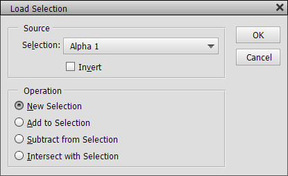
The Load Selection menu item on the panel menu (as well as Select > Load Selection) displays a dialog. On this dialog you can choose the alpha channel that you want to load as a selection from the Selection combo box. The Invert check box inverts the selection in the process. If a selection is already present, you can choose to replace it by keeping the New Selection radio button active. But you can also decide to change the current selection by adding the alpha channel to it (Add to Selection), subtracting the alpha channel (Subtract from Selection) or intersecting both (Intersect with Selection).
Visualization
of the merging process of a channel with a selection or vice versa |
||||
  |
 |
 |

|
 |
Channel
or Selection A and B |
Adding
A and B |
Subtracting
B from A |
Subtracting
A from B |
Intersecting
A and B |
As was previously mentioned you can also load a channel as a selection by holding
down the Ctrl key and clicking on it in the the channels list.
But if a selection already exists you can also add the channel to the selection
by holding down the Ctrl and Shift keys before clicking on
the channel. Similarly you can subtract the channel with the Ctrl and
Alt keys and intersect both by holding down the Ctrl, Shift
and Alt keys.

The Save Selection menu item of the panel menu (as well as Select > Save Selection) allows saving the current selection as a channel as well as changing an existing alpha channel with the help of the selection. To save the selection as a new channel keep the New item in the Selection combo box and enter the name of the channel below.
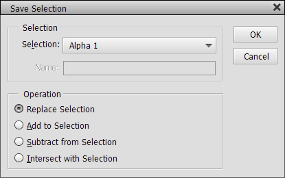
To change an existing channel with the selection choose the channel name from the Selection combo box. Now the three disabled radio buttons at the bottom become enabled and the New Selection radio button is renamed to Replace Selection. As you have guessed, the Replace Selection option simply replaces the existing channel with the selection. The Add to Selection option extends the selected areas of the channel with the selection, the Subtract from Selection option contracts the existing channel and the Intersect with Selection option only keeps the intersection areas of the channel and selection.
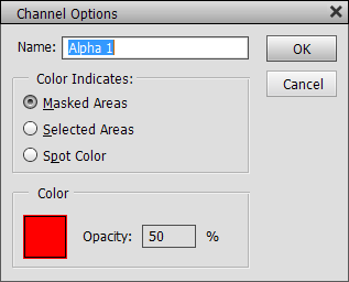
The Channel Options menu item works for all channels except the three color channels. It displays a dialog that provides the similar options as the New Channel dialog above. So you can rename the channel, choose the color and opacity that is used when it is displayed together with the image and decide if this color should cover the masked or selected areas. There is also a Spot Color radio button, but it provides no usable functionality.

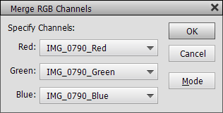
The Split Channels menu item creates three new grayscale documents from an RGB image, each of which contains one of the color channels. This way you can work on each color channel in a separate document window. But as the main document with all three channels was closed, you have to combine the three documents to one again to regain the original color image. This is done with the Merge Channels menu item.
The Merge Channels menu item displays two dialogs in succession. In the first please choose "RGB Color" from the Mode combo box. The other options do not make much sense. Also make sure that Channels is set to 3. After clicking OK, you need to specify the document names that contain the red, green and blue channels in the new dialog. Usually they are already automatically selected, so you only need to click OK. As a result the three grayscale documents are combined to a new RGB document.
Supported
by Photoshop CS2, CC, 2020 and higher
Supported by Photoshop Elements 11 and higher
Requirements: An image has to be opened.
Added in ElementsXXL
6.0
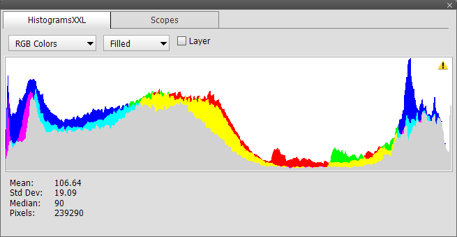
The HistogramsXXL panel is similar to the Histogram panel of Photoshop Elements, but it offers 11 other histogram in addition to the six histograms of Photoshop Elements. It draws histograms in 7 different styles compared to the single style of Photoshop Elements. Additionally you can enlarge the panel window to view the histograms in full detail.
The first combo box at the top of the panel is for choosing the histogram type from "RGB Colors" to "Red/Green (Cr)". Histograms of the following five color models are supported: RGB, CMYK, HSL, Lab and YCbCr. Besides combined histograms of all channels of a color model, you can also view the histograms of individual channels. The second combo box is filled with the seven styles with which the histogram is draw. These include: Filled (just like Photoshop Elements), Filled/Line, Bars, Gradient, Gradient/Line, Line and Dots.
If the Layer check box is activated, only the histogram of the currently selected layer is displayed. Otherwise the histogram of all layers is shown. If a selection is created, your can only see the histogram of the image area, which is surrounded by the selection. To see the histogram of the whole image you have to remove the selection again. An exclamation mark symbol shows in the top right corner. Click it to use the full sized image to calculate the histograms. This is normally not done to avoid slowing down Photoshop Elements.
Supported by
Photoshop Elements 11 and higher, already available in Photoshop
Requirements: An image has to be opened.
Added in Version 11.0
This menu item displays the Layer Comps panel for creating, editing and organizing layer compositions. You can resize the Layer Comps window by placing the mouse at the window border and dragging it.
A layer comp stores the following properties of each layer in a document: visibility, position and layer style. So layer comps allow you to create different looks or designs within one document by making certain layers visible or invisible, by positioning layers differently or by using different layer styles for certain layers. You can also quickly switch between layer comps in order to compare different looks or designs instantly.
If you switch to another document, the layer comps of the last document are not accessible anymore (unless you duplicated the document). So each document has its own layer comps. The layer comps are saved together with the document if you save it to a PSD file.
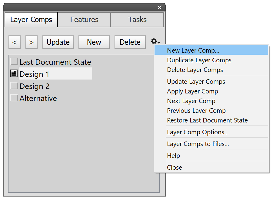
The existing layer comps are displayed in a list box on the Layer Comps panel. Above it there are five buttons as well as a menu icon that displays a menu with further commands. You can also display the same menu as a context menu by right clicking on one of the layer comp items in the list box.
To create a layer comp from the current state of the document, click the New button on the Layer Comps panel or choose the New Layer Comp menu item of the panel or context menu.
On the appearing dialog you can enter a name for the layer comp and decide which layer properties should be applied. If you are unsure, keep all three check boxes activated. If you like, you can also add a comment for explaining the meaning of this layer comp. After clicking OK, you will see the new layer comp in the list of the Layer Comps panel.
To switch between existing layer comps use the < and > buttons or click on the check box of the layer comp in the list. Clicking on the name of the layer comp will only select it, but not activate it. Alternatively you can select a layer comp in the list and choose the Apply Layer Comp menu item from the panel menu. The Previous Layer Comp and Next Layer Comp menu items of the panel menu have the same effect as the < and > buttons. To go back to the last document state that existed before you activated one of the layer comps, activate the Last Document State check box in the list or choose the Restore Last Document State menu item of the panel menu.
To edit the name of a layer comp, redefine which layer properties should be applied or change the layer comp comment, simply double click the layer comp name in the list. You can also select a layer comp and use the Layer Comp Options menu item to do the same. A dialog (similar to the New Layer Comp dialog above) will appear for editing these properties.
You can also duplicate one or more layer comps by selecting them in the list and choosing Duplicate Layer Comps from the panel menu. This is useful if you want to modify existing layer comps for new designs or looks. To delete a layer comp again, select it and click the Delete button or use the Delete Layer Comp menu item.
If you want to modify a layer comp, activate it as discussed above. Then modify the visibility, position or layers styles of the appropriate layers and click the Update button or use the Update Layer Comp menu item. You can also store the current document state as an existing layer comp by selecting the layer comp and clicking the Update button. This will of course overwrite the old contents of the layer comp.
To save each layer comp to a different image file choose the Save Layer Comps to Files menu item. In the appearing file dialog choose the destination folder and file format of the saved files. The name of the saved files will be a combination of the document name and the layer comp name.
Supported by Photoshop Elements 11 and higher
Requirements: An image has to be opened.
Added in ElementsXXL
2.0
Clicking this menu item displays the Path panel for creating, editing and organizing paths. A path is a vector graphic that consists of dots that are connected by lines. A path can be used to create a selection, vector mask or shape layer and can be transformed with the Shape Selection tool. The panel window also includes a tab sheet for switching between the Channels, Paths and Properties panels. They are discussed above and below. To enlarge the panel window move the mouse arrow to the edge of the window and drag its border.

The Pen button switches between the Text On Path tool and the Select tool. The Text On Path tool allows creating and editing paths. On the Tool Options bar you can switch the pen tool between the Draw and Modify modes. With the Draw icon activated you can create or extend a path. The Modify icon displays the dots of the path and lets you move, delete or add new dots. See also Edit > Tools > Pen Tool. If you click the Pen button again, the Select tool is activated, which allows you to scale and rotate the currently selected path. It has the same effect as using Transform > Free Transform from the panel menu.
The Pen Pro button activates ElementsXXL's own Pen Pro tool. For more information on it see the Pen Pro Tool section.
The Save button lets you save the currently selected path. The new path will appear as a new item in the list box of the Path panel. The Delete button deletes the path that is selected in the list box.
The list box of the Path panel displays a Work Path item, which selects a path that was created but not saved yet. If you want to create a new path with the pen tool, better activate the Work Path item to make sure that no existing path is selected and thus modified. The list box also shows all saved path items, so that you can switch between them. Additionally if a layer with a vector mask or a shape layer is selected in the Layers panel (in Photoshop Elements 8 and higher), you will also see its vector mask in the list box.
Even more path features are hidden on the panel menu in the top right corner. Right clicking on the paths list also displays a context menu, which is similar to the panel menu.
The New item of the New Path sub menu creates an path item on the list, which does not contain any path. Use the pen tool to create a path for this new item. If a selection is available, you can use From Selection to create a new path from it. The same is true for the From Shape, From Text and From Vector Mask menu items: If a shape layer, text layer or layer with a vector mask is currently selected in the Layers panel, then each menu item creates a new path from the shape, text or vector mask.
The Deselect Path item makes sure that no path is currently selected. To select a path again click on one of the list box items of the Paths panel. The Save Path and Delete Path commands work just like the Save and Delete buttons mentioned above. The Duplicate Path menu item replicates the currently selected path. The Rename Path item lets you change the name of the selected path. You can achieve the same by double clicking an item in the list box.
The Transform sub menu offers four items (Free Transform, Skew, Distort and Perspective) for reshaping the path. You can also activate these features from the Image > Transform Shape sub menu.
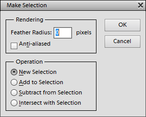
The Make Selection command creates a selection from the current path and also allows combining the current selection with the path. Additionally you can feather and anti-alias the selection. The New Selection option simply replaces the existing selection with the selection that is created from the path. The Add to Selection option extends the existing selection with the path, the Subtract from Selection option contracts the existing selection and the Intersect with Selection option only keeps the intersection areas of the path and selection.
As already mentioned you can also recreate a path from the selection with the New > From Selection menu item. The Convert To Shape item produces a shape layer from the current path after asking for a color.
Fill Path
The Fill Path item of the panel menu fills an image layer with a color or pattern by using the current path. This operation is similar to creating a selection and using the Edit > Fill Selection command. Before applying the Fill Path command make sure that an image layer is selected and that no selection is present, otherwise it may not work.
The Fill Path dialog offers various parameters. You can choose a color or pattern, blending mode, opacity, feathering and anti-alias of the filling operation.
Stroke Path
The Stroke Path item of the panel menu draws the outlines of the current path on an image layer by using a certain tool. This operation is similar to creating a selection and using the Edit > Stroke Selection command, but much more versatile. Before applying the Stroke Path command make sure that an image layer is selected and that no selection is present, otherwise it may not work.
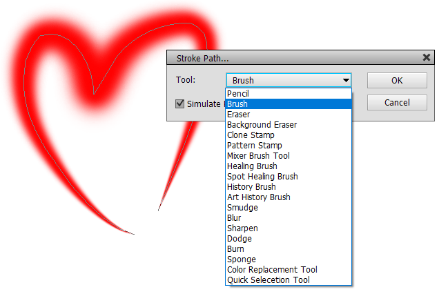
The Stroke Path dialog lets you select the tool that will be used for stroking as well as activate a Simulate Pressure check box for more irregular stroke. The stroke is drawn according to the tool options of the selected tool. So before using the Stroke Path command it is a good idea to select the tool that you want to use and adjust its settings on the Tool Options bar in order to achieve the stroke you had in mind.
Clipping Path
The Clipping Path item of the panel menu is useful if you want to save a part of the image (and not the whole image) to a PDF file. The clipping path can only be seen in the saved PDF and not in Photoshop Elements itself.
The Clipping Path dialog lets you select the path that will be used as a clipping path and define the flatness (meaning softness) of the path curves.
Supported by Photoshop Elements 11 and higher
Requirements: A layer mask, vector mask or filter mask should exists in order
to make use of it
Added in ElementsXXL
3.0

Clicking this menu item displays the Properties panel. You can also double click a layer mask or vector mask thumbnail in the Layers panel to display it. Alternatively you can use the Properties menu item on the Smart Filters, Layer Mask and Vector Mask sub menus of the Layer menu. The panel window also includes a tab sheet for switching between the Channels, Paths and Properties panels. They are discussed above. To enlarge the panel window move the mouse arrow to the edge of the window and drag its border.
The Properties panel lets you adjust the density and feathering of filter masks, layer masks and vector masks non-destructively. Additionally it offers three button with useful commands, but they change the pixels of layer masks and filter masks.
The currently selected mask type is displayed at the top. Additionally one of the mask type icons is selected. If no mask is currently selected the controls on this panel are disabled. In case the current layer contains two or three of these mask types you can click on the mask type icons to switch between them. You can also switch to another mask type by clicking on its thumbnail in the Layers panel. Clicking on the image thumbnail of a smart object selects the filter mask.
Decreasing the Density slider makes transparent mask areas opaque again. In the case of a filter mask the smart filter effect returns gradually. The Feather slider softens the transition between the transparent and opaque mask areas.
The Refine button shows Refine Edge dialog (also available on the Select menu) for adjusting the mask. The Range button displays the Color Range dialog (available on the Select menu too) for recreating the mask. The Invert button simply inverts the mask, so that selected areas are masked and vice versa.
The Mask Options menu item of the panel menu displays a dialog for selecting the color and opacity that are used for displaying the layer mask or filter mask together with the image. It work just like the Channel Options command of the Channels panel
The Load Selection from Mask menu item creates a selection from the mask. If a selection is already available, you can combine the selection created from the mask with the existing selection. You can choose to add the mask to the selection (Add Mask to Selection), subtract it from the selection (Subtract Mask from Selection) or intersect both (Intersect Mask With Selection).
The Apply Mask menu item only works for layer masks and vector masks if the layer is not a smart object. It removes the mask and makes the layer transparent. The Disable/Enable Mask menu item enables or disables the mask. Delete Mask simply deletes the current mask.
Supported
by Photoshop CS2, CC, 2020 and higher
Supported by Photoshop Elements 11 and higher
Requirements: An image has to be opened.
Added in ElementsXXL
6.0


The Scopes panels shows 23 different types of scopes (first combo box) in a negative or positive style (second combo box). Only the RGB, CMYK, HSL and YCbCr color models are used for calculating the scopes. So there is no Lab scope available (see the HistogramsXXL panel), because it would be too time consuming and the YCbCr color model provides a very similar scope.
A scope is a type of 3D histogram, which is popular in video editing, but is also useful for image editing if you know how to read it. To display a scope a regular histogram is calculated for every vertical column of the image. The histogram of every vertical column is then displayed as a single vertical line in the scope from bottom to top (instead of left to right). To fit the histogram data into a one-dimensional vertical line the values of the histogram are expressed as grayscale values. So a dark pixel in the scope represents a low histogram value whereas a very bright pixel means a high histogram value.
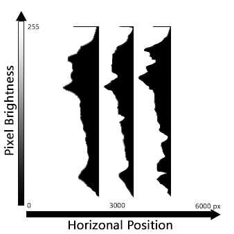
The bottom to top axis of a scope represents pixel values from 0 to 255 (0 to 32768 for 16-bit/channel images). So the pixel values with low brightness are located at the bottom of the scope whereas the pixel values with high brightness are displayed at the top. The brighter a pixel in the scope, the more pixels of that value exist in the image. So a dark spot at the bottom of the scope means that there are not many dark pixels in the image (at that horizontal position). A white spot at the bottom means that many dark pixels are located in the image (at that horizontal position). A white spot at the top means that many bright pixels are in the image (at that horizontal position). Consequentially, a bright area in the middle of the vertical axis means that there are many middle gray pixel values in the image.
Going from left to right in the scope you see how the histograms change from the left to the right hand-side of the image. So if there is a spot horizontally in the middle of the scope, it also means that the histogram values are also physically located in the middle of the image. So the horizontal axis of the scope represents the physical location in the image from left to right. On the other hand, the vertical axis of the scope represents the pixel brightness in the image like the vertical axis of the normal histogram does.
For example, if there is a bright area in the middle of the scope, it means that there is a middle gray object in the middle of the image. If there is a black area in the right bottom of the scope, it means that there are no dark pixels at the right hand-side of the image. If there is a white area in the top left corner of the scope, it means there is a bright object at the left-hand side of the image.
Scopes that display a combination of channels (e.g. the R, G and B channels) at the same time, also contain colors where the vertical histograms of the three channels partially overlap. This indicates that the brightness levels of the color channels do not align completely. This can be used as a guide for color correction by making the scope patterns overlap thus making them appear more gray and less colored.
There are also parade-type scopes, which display the color channels one after the other from left to right. So for the RGB Parade scope the left third of the scope displays the R channel, the middle third displays the G channel and the right third shows the B channel. This also means that the full width of the image is only represented by 1/3 of the space of the scope.
The HSL scopes at the bottom of the first combo box list are again different: For example, the Saturation/Hue scope shows the saturation values vertically and the hue values horizontally. This lets you see the minimum and maximum saturation of different hues. The Lightness/Hue scope shows how dark or bright individual hues are in the image. Finally, the Saturation/Lightness scope displays the saturation range of dark to bright pixel values.
Again as with the HistogramsXXL panel you can activate the Layer check box in order to only see the scope of the current layer instead of the whole image. To see only the scope of a certain image area you can create a selection. An exclamation mark symbol appears in the top right corner. Click it to use the full sized image to calculate the scopes. This is normally not done to avoid slowing down Photoshop Elements.
Supported by Photoshop Elements 11 and higher
Requirements: An 8-bit image has to be opened.
Added in ElementsXXL
5.0
This menu item displays the Smart Filter panel, which lets you add and edit smart filters. You can also run it from the Filter > Add Smart Filters or the Layer > Smart Filter > Edit Smart Filters menu items. It can also be displayed by clicking the smart object icon or smart filter symbol on the Layers panel.

On the Smart Filter tab sheet of the appearing Smart Filter panel you can switch between filter groups with the left list box and choose a filter in the right list box. To apply a smart filter either click the Add button or double click a filter item in the right list. If the current layer is not a smart object, it will automatically be converted into one. Then the filter dialog appears. For applying only smart filters that also support 16-bit/channel images you can activate the Display 16-bit filters only check box. Alternatively you can also use the Filter > Convert For Smart Filters command for creating a smart object and apply the smart filters by choosing a filter item on the Filter menu.

The Edit tab sheet displays the smart filters that are applied to the smart object that is currently selected on the Layers panel. Please notice that new smart filters are added at the top of this list. So the bottom filter was applied first and the top filter last. If you click on another smart object in the Layers panel, the filter list automatically updates to reflect the smart filters of the new smart object.
Double click a smart filter in the list to edit its settings or alternatively select it and use the Edit button at the top. The Blending button shows a dialog for adjusting the blend mode and opacity of the smart filter. The Delete button removes the selected smart filter. To disable an activated smart filter click its eye icon, which is then struck out. To enable it again click the eye icon again. You can also do these four things with the top menu item of the panel menu.
To change the order, in which of the smart filters are applied, you can hold down the left mouse key over one of them and drag it to an new position. If you only need to move one smart filter up or down you can also use the Up or Down panel menu item.
On the panel menu there is also a Duplicate menu item for duplicating the currently selected smart filter. The Add (All) To and Move (All) To sub menus display other smart objects in the same document, to which you can add or move one or all smart filters of the current smart object. This makes it easy to copy or move smart filters and their settings to other smart objects. To copy smart filters to another document please use the Edit > Copy To Document > Selected Layers command to copy the smart object to another document. Then you can use these four sub menus to transfer the smart filters to another smart object within the other document.
Finally, the Help menu item displays this help section and the Close item closes the Smart Filter panel.